
 marzo
16
marzo
16
Etiquetas
The Flight Bar
We can consider that in any Anodizing Plant, the rectifier and its corresponding cooling equipment are the heart of the installation, but what is the use of this heart if it is not able to transport its energy to an aluminium profile, because on the way it encounters an inadequate flight bar?
The function of the flight bar is none other than to transport the current and to carry out this electrical transport with the least possible resistance, all of this by means of a mechanical structure that supports the load of the aluminium profiles or sheets.
Initially, in order to meet these two requirements, some companies built an iron frame with copper plates or tubes to carry the current, which, due to its rigidity, guaranteed compliance with these requirements.

Old iron frame with coupled copper bars and tubes
Soon, the anodizers realised that iron is not the best material for working with flight bars in an anodizing plant. The alternatives to copper and iron were a group of aluminium plates, built with stretchers or welds between them, in order of obtaining the necessary firming for the transportation.
Today we have taken a step forward and, with the increase in the power of rectifiers to between 12,000 and 20,000 amps, the welded aluminium plates have been replaced by structural profiles. There are four types of standard profiles, which vary considerably in size depending on how you work:

Common standard profile types in the flight bar
In the flight bar selection, it is important to take into account the current input, the aluminium section, the length and structure design of the tank. For better understanding of these factors, we will look at them in detail.
1. The current input
Qualanod guidelines establish that contact temperature in the current input area should not exceed 30º C above room temperature. In order to comply with these requirements, we should choose an adequate electrical current pass way, but at the same time we must avoid any electrical resistance that may occur on aluminium surface.
Because of its nature, aluminium forms an insulating natural oxide layer and it can reach 3 nm (nanometres). Electrical current seeks its way into the flight bar and over the time can damage the contact area producing burns and even holes, as shown in the next picture.
 Electrical contact highly degraded by time and current
Since it is not possible to perform interference colouring under these conditions, we will have to avoid this resistance in the current input area, and this can be achieved by protecting the flight bar profile with a copper plate of the same dimensions as the electrical contact that transmits the current to the flight bar.
Electrical contacts are, generally, made of copper, but if aluminium contacts are still used in an installation, it is advisable to change them as soon as possible to copper ones.
The current input to the frame can be from the side if self-tensioning contacts are used, or from underneath the frame as in following pictures.
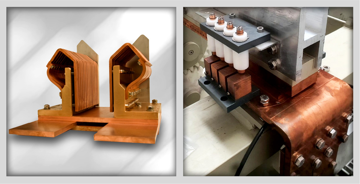
Self-tensioning (left) and under flight bar (right) contacts
In order to achieve a perfect copper and aluminum contact with flight bar, it is necessary to use a 2 mm Al/Cu Bi-metal, creating a kind of sandwich based on the combination ALUMINIUM | BI-METAL | COPPER.

Bi-metal in an aluminium, bi-metal, copper sandwich
If this combination is done correctly, a perfect current input to the flight bar is obtained without any voltage drop and without any need for maintenance in the following years.
Another valid alternative, although more expensive due to the price of the Bi-metal, is to weld it directly to the mainframe, with a total thickness of the Bi-metal of approximately 20 mm as shown in the following image. Moreover, it must be taken into account that this is not a definitive solution.

Bi-metal welded to the mainframe of the flight bar
The decision about connecting electrical current input on one side or on both sides of the flight bar depends mostly on the installation and its production. Whether you want to produce matte silver or electrolytic colors based on our Elcosan DC/AC technology is indifferent, since the differences in the formation of the barrier layer and up to 5 microns in the anodic layer will be levelled in the electrolytic coloration by our Elcosan® technology.
A very different situation arises if the aim is interference coloration, where, based on our extensive experience, we clearly recommend the input of current from both sides. The reason is none other than to ensure more accurate and matched colors at loads, reducing the rejection in the interference.
In practice, it is common for some anodizing plant manufacturers to build their plants with the current input on one side, which is more economical but leaves a problem for the future, especially if they plan to apply interference technologies someday.
2. The aluminium section
The choice of the mainframe is directly related to the rectifier power. The aluminium conductivity compared to copper is practically half and depends on the alloy and the thermal treatment. For an alloy with a maximum 1.5% of alloys, its conductivity is 55% compared to copper and in the case 1.0% of alloys it is 59%. For example, alloy 6060 has a maximum of 2.15% alloy components, somewhat lower than 6063 which has 2.5%.
With these reasons in mind, we recommend 6060 alloy as the most suitable material for extrusion of a mainframe. In practice, we must calculate aluminum with a maximum electrical current flow of 1.0 A/mm2 section. Based on this, we should choose a 10,000 mm2 section if the rectifier has a power rating of 20,000 amp and has an input from both sides, or a 20,000 mm2 section if the input is from one side, all in order to avoid current bottleneck.
3. Tank size
The length of the frame depends directly on the length of the anodizing tank. It is common for an anodizing plant for aluminum profiles for construction industry to have between 700 and 900 cm of free space, reaching in some cases much larger dimensions. Due to this length, it is important to choose a flight bar with a suitable design that reduces strapping and provides stability in handling the load. It is inevitable, in some cases, to increase minimum section necessary for the transportation of the current in reason of the minimum structural requirements of a flight bar.
4. Flight bar structure design
We can consider a modern flight bar design based on the models EX 6400, EXT 8200 and CH 7000. In these tubular mainframes, dirt is not accumulated, contrary to what happens in H-shaped mainframes that require weekly cleaning.
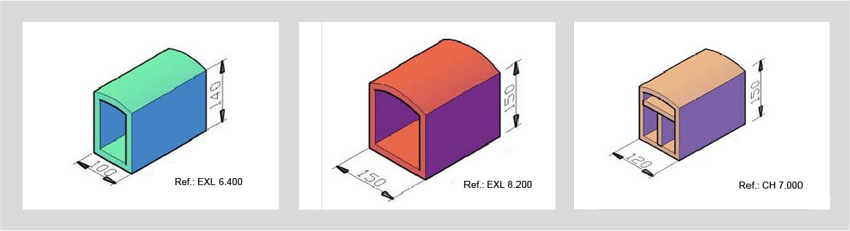
Modern flight bar designs
The new technologies of interference coloring also suggest taking precautions with the extrusion of the structural profile. It is convenient to extrude the frame using only one billet and not linking several billets along the extrusion process. From a technical point of view, this does not present any problems, since nowadays there are 6000 MT presses in Spain that use 520 Kg billets, which allows, in practice, the extrusion of a flight bar of any length in a single run.
